CAD/CAM Engineering
Manufacturing Begins Digitally.
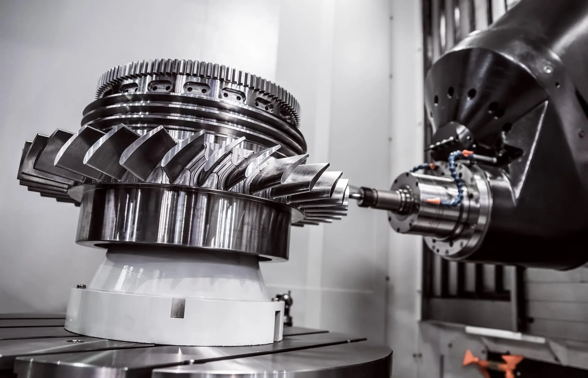
Digital manufacturing workflows connecting component design with efficient, verified machining strategies.
CAD/CAM
Our CAD/CAM workflow connects engineering data with production.
Customer drawings and models are reviewed to develop machining strategies, toolpaths, fixtures and manufacturing sequences designed around efficiency and dimensional control.
From the initial engineering review to final machining, digital tools support every stage of the manufacturing process.
Scope
What It Covers
Digital manufacturing workflows connecting component design with efficient, verified machining strategies.
- Ø1Manufacturability reviewGeometry, tolerances and material are checked against how the part will actually be made.
- Ø2Toolpath programming3-axis, 3+2 and simultaneous 5-axis toolpaths are programmed and verified before cutting.
- Ø3Fixture planningWork-holding is designed around the datum scheme and the number of setups.
- Ø4Process documentationSetup sheets, tool lists and inspection points keep the process repeatable.
Specifications
Capability at a Glance
Part-specific tolerances, sizes and lead times are confirmed in the engineering review, feature by feature.
| Parameter | Capability |
|---|---|
| Quality management system | AS9100:D and ISO 9001:2015 (Intertek, certificate 0255722-00) |
| Engineering services | Manufacturability review, CAD/CAM programming, fixture and process planning |
| Toolpaths | 3-axis, 3+2 and simultaneous 5-axis |
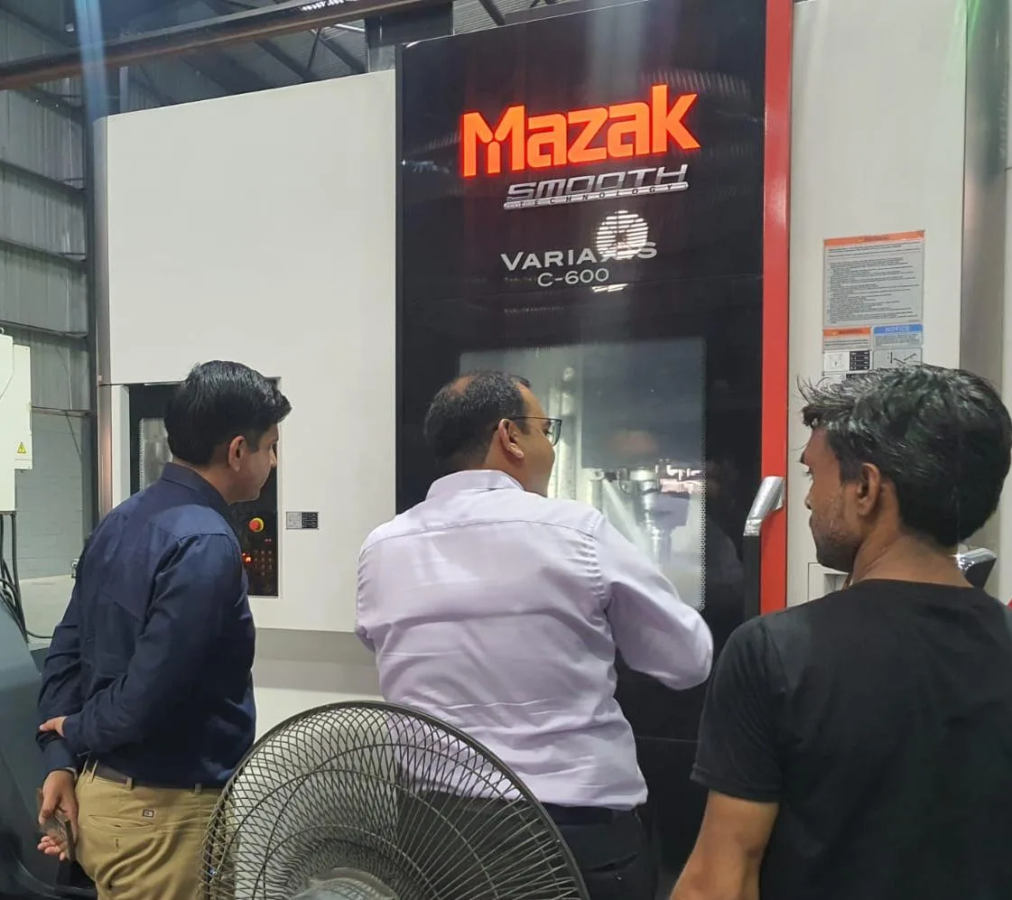
| Machines programmed | Mazak VARIAXIS C-600, Haas EC-400 |
| Files | STEP preferred, with a PDF or DWG drawing; STL for reference geometry |
Engineering Support
Before the Machine Starts.
Every RFQ begins with technical evaluation.
Our engineering team reviews available drawings, models, materials, tolerances, quantities and inspection requirements before determining the manufacturing approach.
This allows potential manufacturing challenges to be identified before production begins.
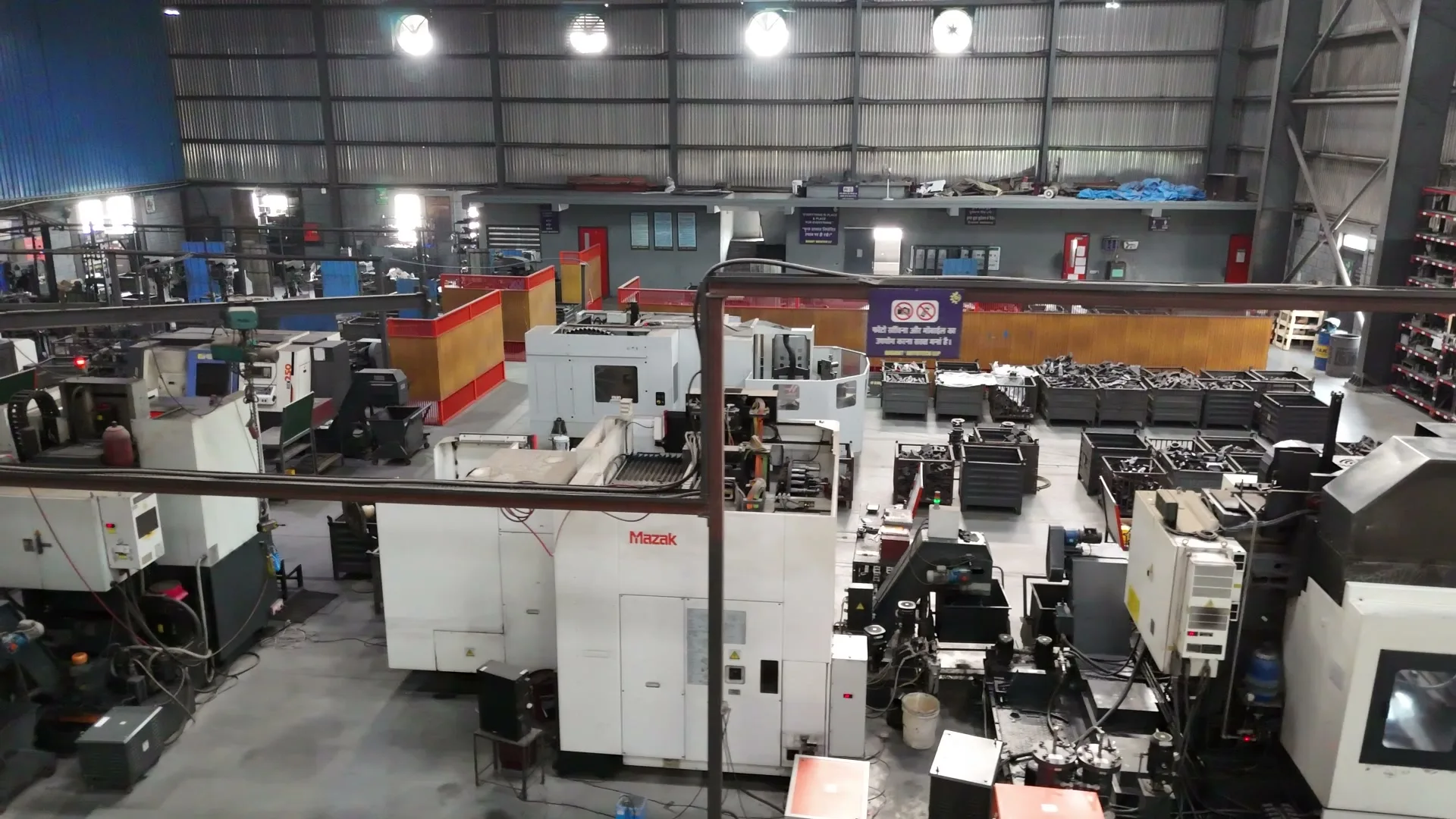
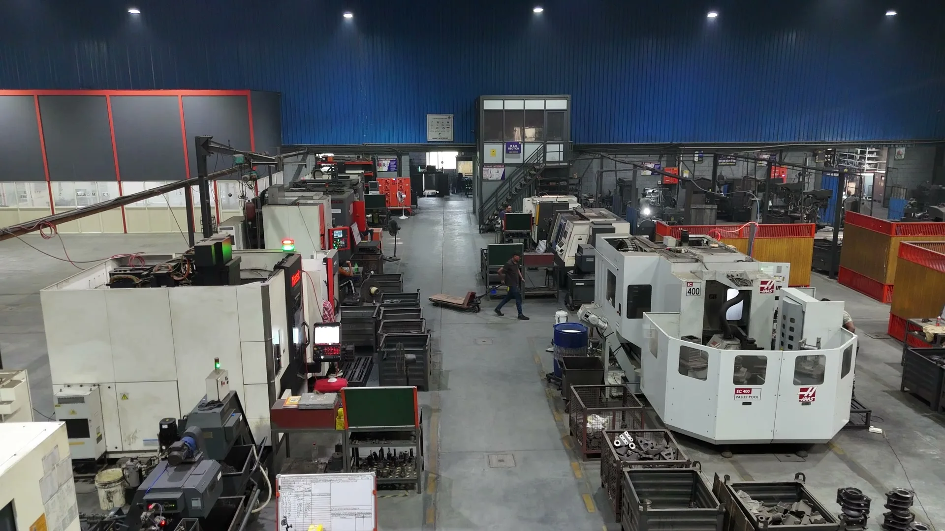
Machining hall, Basant plant
Advantages
Why CAD/CAM Engineering at Basant
- Ø1Problems found on screenCollisions, thin walls and unreachable features are resolved before material is cut.
- Ø2Design for manufactureWe flag features that add cost or risk and suggest alternatives where the function allows.
- Ø3RepeatabilityA proven program and fixture produce the same part on the next order.
- Ø4Model-based workMachining and inspection both start from the same CAD data.
- Ø5Shorter developmentPlanning the whole route up front removes iterations at the machine.
- Ø6Configuration controlDrawing revisions are tracked so the part made matches the revision ordered.
Process
How the Work Runs
Every job follows the same controlled sequence, from the first look at the drawing to the recorded result.
- Ø1Data intakeModels and drawings are received and checked for completeness and revision.
- Ø2ReviewManufacturability questions are raised with you before quotation.
- Ø3PlanningSetups, fixtures and tooling are defined.
- Ø4ProgrammingToolpaths are created and verified.
- Ø5ReleaseThe process is documented and released to the shop floor.
FAQ
Common Questions
- A 3D model (STEP) together with a 2D drawing (PDF or DWG) that carries the tolerances, material, finish, quantity and quality requirements. If you only have a sample part or a sketch, send what you have. The engineering review will tell you what else is needed.
- Yes. The engineering review highlights features that are difficult or expensive to machine or measure, and proposes changes where function allows. Nothing is changed without your approval.
- STEP is preferred for 3D models, with a PDF or DWG drawing for tolerances and notes. STL files are accepted for reference geometry. Several files can be sent together as a ZIP archive.
- Both. Parts are programmed and inspected in the units of your drawing.
- Achievable tolerance depends on the feature, the material and the size of the part, so we confirm it feature by feature during the engineering review instead of quoting one headline number. Mark the critical dimensions on your drawing and we will tell you how each will be machined and measured.
- Yes. Request an NDA from the contact page before you upload anything; files sent through this website are stored privately and are only seen by the team reviewing your inquiry.
More Capabilities
Scan. Engineer. Machine. Inspect.
One integrated engineering workflow, on one site.
- 01 /5-Axis MachiningComplex, multi-face components machined in fewer setups, with the datum structure kept intact.
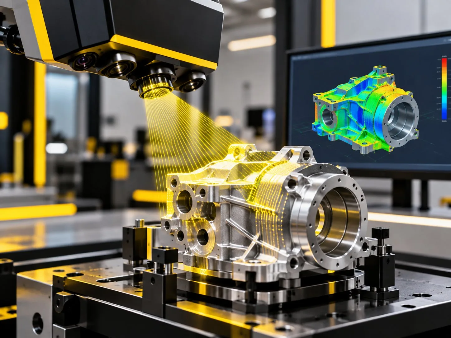
- 02 /Reverse Engineering & 3D ScanningFrom a physical sample to a model and a drawing you can manufacture and inspect against.
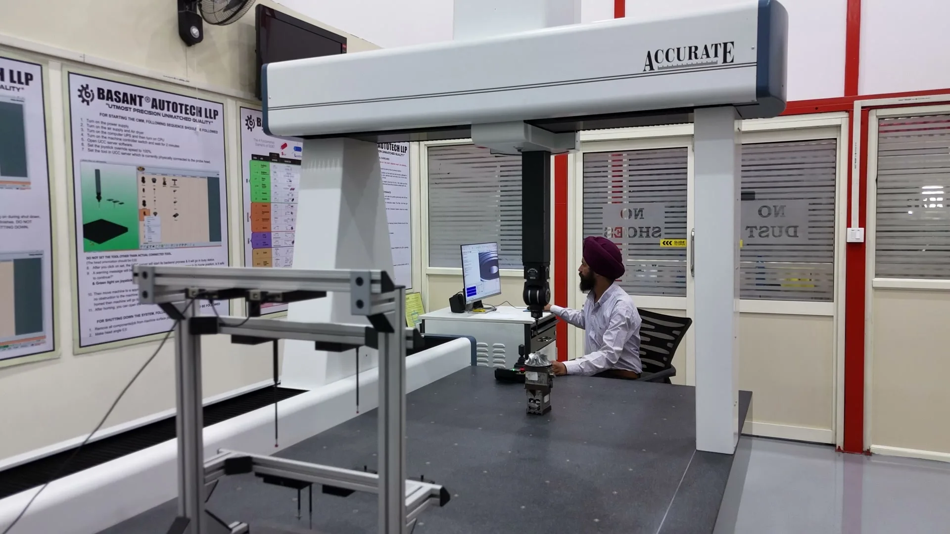
- 03 /CMM & Precision MetrologyDimensional inspection that proves a component meets its drawing, and records it.
- 04 /3D Printing & PrototypingPrototype parts and fit-check models that shorten the path from a design to a machined, inspected component.